Description

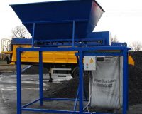
16 HYDRATION TANKS
For dry legume, each with a capacity of 1,000 kg.
Bottoms slope to a point and exit is through pneumatic gate valves for each tank. General pipe collector to remove pulses with the water, connecting the two tanks. Return line to the rear with pneumatically operated individual access to each tank. AISI 304 stainless steel construction.
1VACUUM EXTRACTOR TANK
- For bringing the pulses from the hydration tanks.
- Liquid mechanical vacuum pump with a water storage tank and recirculation pump in a closed circuit.
- A storage tank with gate operated by pneumatic cylinder rod.
- Level probe and vent valve to break the vacuum seal.
- The level probe in a storage tank to allow the door to be opened depending on the quantity of product.
- Control panel for all system operations.
- AISI 304 stainless steel construction.
1 HOSTING POOL
- For collecting the product from the extractor and feeding it into the Rotary Blancher.
- Inferior tank with perforated sheeting on the floor to allow passage of water.
- Polypropylene band conveyor with buckets to get the product.
- Recirculating pump to return water to hydration tanks.
- Tank with adjustable overflow, stopcock, etc.
- Movement via gear motor with variable-frequency drive
- AISI 304 stainless steel construction.
1 ROTARY BLANCHER
- With approximate production capacity for pulses of 4,000 kg/h.
- Basic measurements: length 4,000 mm and diameter 1,800 mm.
- Consisting of: Rotary drum with removable Ø 3 mm perforated sheeting for ease of cleaning.
- Fitted with a worm to force the product through the machine and deflector fins for floating products (no central shaft). Movement via 2 hp mechanical gear motor with electronic variable drive.
- Tube heat exchanger on the outside of the blancher to heat the water indirectly and recycle the condensates.
- 3 hp pump to recirculate the water from the tank through the heat exchanger and create a counterflow for uniform temperatures.
- Incorporating spray in the center of the worm.
- Digital temperature control with modulated pneumatic valve and filter.
- Central electrical panel.
- Footbridge with steps and handrails on both sides of the equipment.
- AISI 304 stainless steel construction except for movement and temperature automata.
1 VIBRATING CONVEYOR – VIBRATORY TRAY
- For collecting the product from the blancher and feeding it evenly into the cooling hopper.
- Tray 2,000 mm long by 1,000 mm wide made from perforated sheeting on silent block base.
- Movement via two electric motor vibrators.
- AISI 304 stainless steel construction except for motor vibrator base.
1 COOLING AND INSPECTION HOPPER
- 6,000 mm long, water immersion system.
- Perforated mesh conveyor belt to transport the product.
- Initial collection area, lowering area for submerging the product in the water,
- immersion area, exit area and area with a length of 2,000 mm for inspection.
- Hopper with upper overflow and gate to take skins to one end.
- Centrifugal pump to generate water flow.
- Bar of network sprays at the end of the ascent for rinsing the product and renewing
- the water in the hopper to keep it from heating up.
- Movement via gear motor with a variable-frequency drive.
- AISI 304 stainless steel construction.
OPTION A FOR FILLER MACHINE
1 LINEAR FILLER
Filler for glass jars and metal cans.
Consists of a circuit for feeding and filling containers with the following components:
FEED ELEVATING HINGE for transporting the product to the jar/can filling area, which consists of two roller chains with fins and plates joining them to form buckets. Perforated sheeting base on elevating belt to drain the product before it reaches the canning area. Perforated sheeting double bottom supplemented with cleanout, stopcocks, etc.
FILL CONVEYOR HINGE for a product, consisting of an 800 mm wide conveyor hinge to distribute the product along the canning area. Polypropylene mesh.
The mechanical system for regulating can fill height.
CONVEYOR HINGE for feeding the empty jars/cans to the filling zone and removing the filled jars/cans.
CONVEYOR HINGE for collecting the surplus product and returning it to the
product feed elevating belt area so that it can re-enter the filling cycle. Intralox
Series 800 polypropylene mesh.
Horizontal VIBRATOR to obtain the desired weight in jars/cans.
HINGE joining conveyor to elevating belt with dual-direction control for removing a product in the event of jar breakage.
Vertical VIBRATOR for filling jars/cans.
Movement via six variable speed drives, coupled with four electronic variable
drives. Central electrical panel for all movements with the relevant buttons, contractors, breaker switches, etc.
Made in stainless steel AISI 304 excepting movements and plastic parts.
OPTION B FOR FILLER MACHINE
1 REDLER RAISER
- for transporting the product to the can filling area, which consists of two roller chains with fins and plates joining them to form buckets.
- Perforated sheeting base on elevating belt to drain the product before it reaches the canning area.
- Perforated sheeting double bottom supplemented with cleanout, stopcocks, etc.
- Movement via gear motor with a variable-frequency drive.
- Made in stainless steel AISI 304 excepting movements and plastic parts.
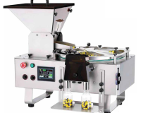
1 ROTARY FILLER
Automatic rotary filling of telescopic glass.
Consisting of:
- A plate of 1.700 mm. diameter.
- Centralized lubrication for all grease points.
- Motorized upper brush that place product at plate level.
- Inlet/outlet hinge conveyor belt of 100 mm. Of width and system of synchronization for cans.
- Adjustable upper guides over the plate with a scraper to feed product towards telescopic glass area.
- Manual regulation in height of the telescopic glass so that allows regulating the quantity of product to be filled.
- The format of the machine made with polyethylene food.
- Centralized electric panel with a frequency converter to regulate speed and synchronize movements with programmable automata for all safeties of the machine.
- Built according to CE
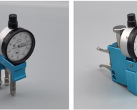
1 LIQUID DOSING MACHINE
- Overflow type, with a length of 2,000 mm.
- Hinged conveyor belt 3,000 mm long for feeding the can to the sealer.
- A lower fluid storage tank with minimum and maximum level probes.
- Recirculation pump from lower tank to an upper filling channel.
- Hinged conveyor belt for cans operated by variable speed drive-gear motor.
- AISI 316 stainless steel construction.
1 SEAMER MACHINE SOMME
1 CONVEYOR HINGE
- Conveyor hinge sliding acetal
- 8.000 mm. long by 100 mm. wide with one 90º curve.
- Adjustable guides in wideness for different formats.
- Foot with adjustable height.
- Movement via 0,5 Hp worm wheel gear motor.
- AISI 304 stainless steel construction except for movement and plastic parts.
1 SEMI AUTOMATIC LOADER
For placing cans into baskets.
Consisting of:
- Sliding polypropylene mesh conveyor belt 4.000 mm long by 1.000 mm wide.
- Pneumatic preformed sheeting stop system prior to entry in the filling zone.
- Hydraulic unit with 2 hp motor. double scissor to raise/lower the bottom of the filling cage.
- 1000 x 1000 mm magnetic sheet (for metal cans of up to 5 kg and glass jars).
- The mechanical system for lifting, lowering and moving the magnetic sheet.
- Central electro-pneumatic panel for all machine functions with PLC.
- AISI 304 stainless steel construction except for movements, plastic parts, and hydraulic unit.
3 HORIZONTAL RETORT
For commercial sterilization/pasteurization of food products packed hermetically in: glass, tin, heat-sealed and thermoformed trays, bags, plastic containers, etc.
Model: AHE 6J/1P – PTC
Capacity: Six 920 x 920 x 920 mm baskets
Diameter: 1,400 mm
System: Water Cascade
AISI 304 stainless steel construction
Equipment built according to European Union Directive 97/23/EC.
Cascade system:
The water deposited in the base of the body of the autoclave is aspirated at
different points by a high-flow pump, which sends it to the plate heat exchanger before depositing it in the distribution tray area to ensure uniform and steady
pouring over all containers and homogenizing the temperature inside the machine and the containers.
The high-performance exchanger allows you to carry out thermal transfer in the heating, sterilization and cooling processes both quickly and gradually so as to avoid thermal shock. It also allows you to recover the condensate and reuse the cooling water for other factory processes as they have absolutely no organic load, having been in a closed circuit.
Daily water consumption is around 700 litres. This is the water we recirculate in the autoclave from the first process onwards, which we recommend emptying at the
end of the day.
All processes are controlled automatically by a microprocessor with a touch screen.
GENERAL DESCRIPTION
- Total length with the door open: 8,070 mm
- Total width: 2,530 mm
- Height: 2,380 mm
- Quick-closing bayonet catch door with hand wheel for opening/closing.
Adjustment and safety fastening device sensors that prevent the cycle from
starting should it not be totally closed and do not allow it to be opened if
there is pressure inside the autoclave.
- Motorized basket conveyor belt with manual operation. Movement via 1.5 hp gear motor.
- Two roller bearing tracks for easy movement of baskets inside the autoclave.
- Internal probe to calculate Fo (internal product temperature). The equipment has three PT-100 probes and two level conductivity probes.
- Water level control system in the interior through the magnetic level.
- Body and base lined with fiberglass thermal insulation blanket with a thickness of 60 mm, coated in stainless steel sheeting with mirror finish.
- Door protected with thermal insulation and stainless steel lid.
- Filter protecting the internal water recirculation circuit.
- Guide for introducing carriages into the autoclave.
- The possibility of recovering the condensate, thus obtaining savings of 12-15% in steam consumption.
- Microprocessor mounted on a stainless steel panel.
- Seven pneumatic modulating valves with filters and check valves for fluid inflow and outflow.
– Steam inlet – primary circuit
– Water inlet – primary circuit
– Cooling water outlet
– Condensate output
– Air inlet
– Recirculation water inflow
– Pressure release
– Built as per EC regulations for pressure equipment.
CONTROL AND SAFETY FEATURES
- Pressure switch to regulate the inlet and outlet pressure of the water in the pump.
- The magnetic level system to determine the water level inside the equipment.
- Pressure gauge indicating the pressure values inside the autoclave.
- The thermometer in the upper main section of the water flow.
- Two spring-loaded safety valves.
- Alarm (siren) for any process malfunction.
- End-of-process alarm.
CHARACTERISTICS OF AUTOCLAVE 6J/1P ( SIX BASKETS)
- Maximum working pressure 4 kg/cm2
- Maximum working temperature 151 ºC
- The thickness of stainless steel plate 6 mm.
– CHARACTERISTICS OF HEAT INTERCHANGER
- Trademark SPX
- Calorific Power 2.200.000 kcal/h
- Working pressure 6 kg/cm2
– CHARACTERISTICS OF PUMP
- Trademark: GRUNDFOS
- Power 15 cv. ( 11 KW )
- Volume 210.000 lts/h
- Special closing for temperature
AUTOMATION DEVICE FEATURES
Process Control Unit: temperature, pressure, time, level and Fo/Po factor with basic
capacity for 100 programs.
Microprocessor with TOUCH SCREEN – TS
Graphic LCD terminal with:
– Dynamic, real-time display of process underway.
– Graphical display of curves for pressure, temperature, autoclave,
internal product temperature, readings, Fo factor, all selectable
according to user-defined settings.
– Display of all variables of the programme underway.
– Display of the edited programme library.
– Direct display of each programme on a single template.
– An indication of warnings and alarms in a cumulative list.
– An indication of any event, warning or alarm with flashing messages.
– Circular inspection hole Ø 248 mm, with two variables: a PT-100 probe
temperature and another for pressure.
Rotation: 1R/24 h.
220 V/50 Hz.
– Mounted on a stainless steel panel.
– Malfunction alarm and end-of-cycle siren.
50 AUTOCLAVE BASKETS
Constructed in stainless steel blank sheeting with reinforcements in the same
material.
Loose bottom made from perforated sheeting for automatic filling and emptying of baskets.
AISI 304 stainless steel construction
50 CARRIAGE, to transport baskets.
Nylon wheels, two fixed and two rotary wheels placed in a cross to easy the
transport. Guides for the containers and security lock.
Made in stainless steel.
300 POLYPROPYLENE DIVIDERS
Perforated 900 x 900 mm polypropylene dividers with a thickness of 4 mm and 20 mm holes.
1 SEMI-AUTOMATIC UNLOADER
- For placing cans out of baskets.
- Sliding polypropylene mesh conveyor belt 3.000 mm long by 1.000 mm wide.
- Hydraulic unit with 2 hp motor. Double scissor to raise/lower the bottom of the filling cage. 1000 x 1000 mm magnetic sheet (for metal cans of up to 5 kg and glass jars).
- The mechanical system for lifting, lowering and moving the magnetic sheet.
- Central electro-pneumatic panel for all machine functions with PLC.
- The triple-row hinged conveyor belt at various speeds with lateral vibration system to arrange jars/cans in a single line.
- AISI 304 stainless steel construction except for movements, plastic parts, and hydraulic unit.
1 CONVEYOR HINGE
- Conveyor hinge sliding acetal
- 15.000 mm. long by 100 mm. wide.
- Adjustable guides in wideness for different formats.
- Foot with adjustable height.
- Movement via 0,5 Hp worm wheel gear motor.
- AISI 304 stainless steel construction except for movement and plastic parts.
1 SEMI-AUTOMATIC PALLETIZER
Consists of the following elements:
– Accumulation table
– Of 3,500 mm. Of length and polypropylene mesh belt of 1,250 mm.
of wide.
– Movement via 1 Hp gear motor with variable-frequency drive
– A pneumatic system to form the plate when working palletizing and
opening system of lateral guides to avoid catching the nerves of the
packages up.
– AISI 304 stainless steel construction excepting movements and
plastic parts.
– Rigid Support- to support the magnet plate and the carriage of lateral
displacement.
– Carriage of lateral displacement.
– Movement via racks and pinions driven by brake motor.
– 1200×1200 mm. a permanent magnetic plate of high capacity with
lifting and lowering movement through a column with rack and pinion
via gear motor brake.
– A pneumatic system to take or to remove cans depending on the chosen
cycle.
– Control panel for all movements of the cycle.
– Controlled via programmable automata and the possibility to choose a manual or automatic cycle.
– Sensors to detect different phases of the cycle and send signals to the control panel.
– Security sensors with blocking option in case of electric failure.
– Frequency variations for all movements of the magnet plate in a way that
allows modified times and also regulate production.
– Electrical and pneumatic installation of the machine.
1 CANNING LIQUID PREPARATION EQUIPMENT GROUPS TO PREPARE COVERING LIQUID ( BRINE )
DOUBLE BOTTOM TANK for the preparation of canning liquid, 900 mm in
diameter with a capacity for 500 L.
Jacket to introduce steam and heat the liquid.
Recirculation PUMP with bypass for mixing in a 500-L tank and taking it to the upper tanks.
DOUBLE BOTTOM TANK, 1,300 mm in diameter and 1,000 mm high with a
the capacity of 1,200 ltrs, for liquid storage.
Jacket to introduce steam and keep the liquid at the desired temperature.
Electric stirrers with movement via 1 hp gear motor to keep the liquid moving.
Pneumatic PRESSURE CONTROL VALVE to regulate inlet steam pressure to the three double-bottom tanks.
CONTROL PANEL with independent digital temperature control for each tank and contractors for the stirrers and recirculation pump.
Pneumatic modulating valves to control the inlet of steam to each tank.
RAISED BASE to hold the two double-bottom tanks, which gravity-feed the
dispenser, with access ladder, guard rails, etc.
Flooring and steps with anti-skid plastic treads.
AISI 304 – AISI 316 stainless steel construction except for movement and
temperature automata.
1 SEMI-AUTOMATIC EMPTY CAN FEEDER
SEMI-AUTOMATIC DEPALLETIZER MACHINE
Drag type for metal cans and glass jars
Feeder comprising:
- Motorized pallet-lifting system using chains with photocells and safety and position sensors.
- A system to remove the jars/cans from the pallet layer by layer using a drag conveyor belt with detectors and position limit switches.
- Polypropylene mesh buffer table 1,250 mm wide by 3,500 mm long with capacity for two layers.
- Adjustable side tracks and movement via mechanical variable speed drive.
- Triple-row hinged conveyor belt at different speeds to remove jars/cans one by one.
- Movement via gear motor and electronic variable speed drive with a potentiometer.
- Motorized roller conveyor belt to release the pallet and introduce it into the feeder with movement via gear motor.
- Pneumatic gate allowing the empty pallet to exit the machine and for the filled pallet to be fit securely without getting stuck as it is raised.
- Central electrical panel with PLC to regulate all movements, automatically synchronizing them.
- The basic control panel in the working area with a potentiometer to regulate speed, manual or automatic selection and basic controls for manual operation.
- AISI 304 stainless steel construction except for movement and temperature automata.
OVERHEAD FEEDER CONVEYOR HINGE
- To take cans from the exit of the feeder-depalletizing machine and transport them to the jar/can lowering machine.
- 15,000 mm long to connect it to the Lowering Machine-Washer.
- Constructed from folded steel sheeting to form the chassis and adjustable tracks to adapt the format.
- Tilt/height adjustable feet.
- Movement via 1 hp worm wheel gear motor
- Sliding acetal hinged conveyor.
- Made in stainless steel AISI 304 excepting movements and plastic parts.
JAR/CAN LOWERING MACHINE-WASHER – PACKAGES LOWERING DEVICE
Consisting of the following:
- Lowering mechanism formed by two lateral conveyor belts and a chain guided by rubber fingers to hold the jars.
- Two 180º curves in a vertical position to turn the jars upside down and the right way around again before feeding them on to the conveyor belt.
- Washing area of 1,000 mm in the centre of the downward slopes when the jars are turned upside down, with sprays underneath and a 1 hp electric fan.
- Adjustment of slope width for different container formats using gear pinions and chains.
- Movement of each downward slope by means of two 1 hp gear motors with electronic variable speed drive on the empty jar/can Feeder panel.
- Made in stainless steel AISI 304 excepting movements and plastic parts.
- Protections meet safety regulations.
CONVEYOR HINGE
- Conveyor hinge sliding acetal
- 5.000 long by 100 mm. wide
- Adjustable guides in wideness for different formats.
- Foot with adjustable height.
- Movement via 0,5 Hp worm wheel gear motor.
- Aisi 304 stainless steel construction except for movement and plastic parts.
1 SEMIAUTOMATIC DEPALLETIZER
Consists of the following elements:
– Accumulation table – Depalletizer
– 3,250 mm. of length and polypropylene mesh belt of 1,250 mm. of
wide.
– Movement via 1 Hp gear motor with a variable-frequency drive.
– The conveyor of 3 hinge chains at a different speed to place cans one by
one.
– Lateral Vibrator
– AISI 304 stainless steel construction excepting movements and
plastic parts.
– Rigid Support- to support the magnet plate and the carriage of lateral
displacement.
– Carriage of lateral displacement.
– Movement via racks and pinions driven by brake motor.
– 1200×1200 mm. a permanent magnetic plate of high capacity with
lifting and lowering movement through a column with rack and pinion
via gear motor brake.
– The pneumatic system to take or to remove cans depending on the chosen cycle.
– Control panel for all movements of the cycle.
– Controlled via programmable automata and the possibility to choose a manual or automatic cycle.
– Sensors to detect different phases of a cycle and send signals to the control panel.
– Security sensors with blocking option in case of electric failure.
– Frequency variations for all movements of the magnet plate in a way that
allows modified times and also regulate production.
– Electrical and pneumatic installation of the machine.